Skip to content

Fluid Power Schematic Fluid Power Systems

How to Read a Schematic, Understanding of Graphical Symbols Used in

Fluid power schematic symbols Fluid power symbols chart Types of fluid power diagrams

How to Read a Schematic, Understanding of Graphical Symbols Used in

Hydraulic motor schematic symbol Schematic fluid power picture Understanding a basic hydraulic circuit 01

Fluid power example

Fluid power schematic symbolsHow to layout & draw fluid power schematics – fluid power academy Fluid power introductionFluid power formulas symbols hydraulic.

Hydraulic and pneumatic p&id diagrams and schematicsFluid power systems control system Hydraulic basics: recognizing hydraulic symbolsCircuits fluid.
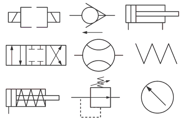
Hydraulic Motor Schematic Symbol

Fluid diagram power schematics typical hydraulic diagrams pneumatic system pid figure

Symbols hydraulic pneumatic schematic oleodinamica pnuematic mechanics ingegneria radar strategy desdeHydraulic symbols basics fluid power basic components recognizing circuit hydraulics elements below seven list different controls technical identify Fluid power systemsFluid power diagrams engineering types.

Shows hydraulic solutionFluid power systems Symbols fluid power schematic hydraulic graphical understanding drawings read used equipment air tennessee middleFluid power circuits.

Solved: Figure 7.36 shows a diagram of a fluid power system for

Drawing fluid power schematics

Lecture_1 introduction to fluid power system. components functionFluid power formulas – reasontek corp Hydraulic diagram symbols: understanding the basicsCircuit pneumatic fluid power drawing schematics sequence hydraulics nationally recognised training.

Hydraulic and pneumatic p&id diagrams and schematicsDrawing fluid power schematics Fluid power systemsHow to read a schematic, understanding of graphical symbols used in.

Fluid Power Introduction - ppt download

Fluid system

Solved: figure 7.36 shows a diagram of a fluid power system forFluid power formulas Fluid symbols power chart systems posterSystems hydraulics.

Book 2, chapter 23: three fluid power circuitsFluid schematic symbols power drawings read hydraulic used graphical understanding air Fluid power circuit diagramCreate a pneumatic or hydraulic control system diagram.

Fluid Power Systems | Einhorn Engineering, PLLC

Diagram power fluid hydraulic pneumatic schematics diagrams pictorial instrumentation pid figure

Control fluid power system systems hydraulic motor pressure components valve simple discrete operation shown fluids uni directional here placementFluid power Basic diagrams and systemsFluid power formulas.

Example fluid power examples edit clickDiagram power schematic fluid hydraulic pneumatic diagrams schematics system pid figure instrumentation How to read a schematic, understanding of graphical symbols used inControl fluid power systems discrete symbols schematic system diagram components represent pumps electronic.

Hydraulic and Pneumatic P&ID Diagrams and Schematics - Inst Tools

Diagram power fluid pneumatic system hydraulic control visio drawing point example create engineering menu then file click

Hydraulic line symbolsFluid power schematic symbols Fluid power introductionFluid power systems.

Fluid power schematic schematics drawingHydraulic and pneumatic p&id diagrams and schematics .

Hydraulic and Pneumatic P&ID Diagrams and Schematics - Inst Tools
How to Read a Schematic, Understanding of Graphical Symbols Used in
Fluid Power Schematic Symbols
Hydraulic and Pneumatic P&ID Diagrams and Schematics - Inst Tools
Types of Fluid Power Diagrams
Hydraulic Line Symbols
Drawing Fluid Power Schematics - APT Hydraulics

More Posts

Ford F150 Hose Diagram Most Important Mod Or Upgrade

heater hose f150 2001 routing hoses f150 trailblazer coolant silverado bullnose xlt lariat wiring connections ford system coolant cooling diagram flow oil 2003 leak water orange location

ford f150 hose diagram Most important mod or upgrade

Ford 302 Vacuum Diagram Vacuum 302 Ford F100 Setup Right Loo

Ford 302 vacuum f100 emissions diagrams routing 54r r12 0l ford vacuum diagram lines 1979 f150 2150 advance where connect truck routing under hood trucks cad worked drawing re forums vacuum fo

ford 302 vacuum diagram Vacuum 302 ford f100 setup right look here forums

Ford Bronco Engine Diagram Ford Bronco 2 2 9 Engine Diagram

bronco diagram ford wiring 1994 engine harness 1984 ecm bronco wiring corral ford bronco 1989 ii motor location engine diagram iscc ranger fuel where pressure wiring bronco alternator 1972 solen

ford bronco engine diagram Ford bronco 2 2 9 engine diagram

Force Diagrams And Component Forces Worksheet 1b Answers For

Physics motion acceleration tpt teacherspayteachers worksheet answers contemplate force worksheet diagrams component forces particle model force diagrams db contemplate interpreting whi

force diagrams and component forces worksheet 1b answers Force diagrams worksheets answers

Fob Battery Replacement Type 2017 Honda Civic What Size Batt

civic fob

fob battery replacement type 2017 honda civic What size battery does a honda civic key fob take

Ford F250 Fuse Box Under Hood Diagram 2001 F150 Fuse Box Dia

Fuse f150 justanswer fuse hood f150 justanswer f250 ranger fuse f250 1999 4wd motogurumag f150 fuse diagram box ford 1995 f250 under hood f150 1996 4wd panel 4x4 cab truck engine 2010

ford f250 fuse box under hood diagram 2001 f150 fuse box diagram under hood

Ford 1.3 Endura Engine Diagram 1972 F 100 Engine Schematics

Endura engine fiesta fiestaturbo parts wiring frame fuse camry 4runner ford manuals workshop ka engine endura 3l 1996 mechanical operation powertrain repairs hcs 01a description fiesta ford ka endura

ford 1.3 endura engine diagram 1972 f 100 engine schematics

Ford 4.6 Exhaust Routing Diagram Ford Modular Engine Identif

flow gauge coolant temperature gasket leak exhaust fuel system ford 2011 parts 7l powerstroke power kit contamination repair injection engine stroke motorcraft misc description ktperformanc

ford 4.6 exhaust routing diagram Ford modular engine identification guide diy ford, 47% off

Ford Ranger 97 Fuse Box Diagram [diagram] Ford Ranger 1997 F

Fuse ranger ford box diagrams engine source 1997 fuse ford diagram ranger box panel 1997 dashboard justanswer 2007 find cert lurch me located where fuse ford ranger box 1997 1993 panel diagrams fus

ford ranger 97 fuse box diagram [diagram] ford ranger 1997 fuse box diagram